Types of capacitor
Types of capacitor
From Wikipedia, the free encyclopedia
This article is about commercial discrete capacitors as customary components for use in electronic equipment. For the physical phenomenon, see capacitance. For the explanation of the units of measure of capacitance, see farad.
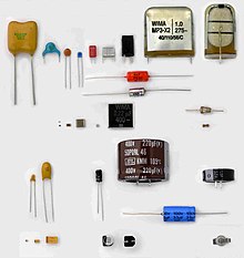
A capacitor (formerly known as a condenser, and prior to that known as a permittor) [1] is a passive two-terminal electrical componentthat stores electric energy in an electric field. The forms, styles, and materials of practical capacitors vary widely, but all contain at least two electrical conductors (called "plates") separated by an insulating layer (called the dielectric). Capacitors are widely used as parts ofelectrical circuits in many common electrical devices.
Capacitors, together with resistors, inductors, and memristors, belong to the group of "passive components" used in electronic equipment. Although, in absolute figures, the most common capacitors are integrated capacitors (e.g. in DRAMs or flash memory structures), this article is concentrated on the various styles of capacitors as discrete components.
Small capacitors are used in electronic devices to couple signals between stages of amplifiers, as components of electric filters and tuned circuits, or as parts of power supply systems to smooth rectified current. Larger capacitors are used for energy storage in such applications as strobe lights, as parts of some types of electric motors, or for power factor correction in AC power distribution systems. Standard capacitors have a fixed value of capacitance, but adjustable capacitors are frequently used in tuned circuits. Different types are used depending on required capacitance, working voltage, current handling capacity, and other properties.
Contents
[hide]- 1 General remarks
- 2 Types and styles
- 3 Comparison of types
- 4 Electrical characteristics
- 4.1 Series-equivalent circuit
- 4.2 Standard capacitance values and tolerances
- 4.3 Temperature dependence
- 4.4 Frequency dependence
- 4.5 Voltage dependence
- 4.6 Rated and category voltage
- 4.7 Impedance
- 4.8 Inductance (ESL) and self-resonant frequency
- 4.9 Ohmic losses, ESR, dissipation factor, and quality factor
- 4.10 Limiting current loads
- 4.11 Insulation resistance and self-discharge constant
- 4.12 Leakage current
- 4.13 Microphonics
- 4.14 Dielectric absorption (soakage)
- 4.15 Energy density
- 4.16 Long time behavior, aging
- 4.17 Failure rate
- 5 Additional information
- 6 Market segments
- 7 See also
- 8 References
- 9 External links
General remarks[edit]
Capacitors are a good example of the fact that even the simplest device can become complicated given 250 years of evolution.[2]
Theory of conventional construction[edit]
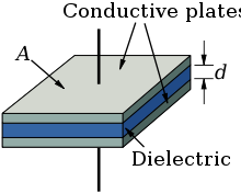
In a conventional capacitor, the electric energy is stored statically by charge separation, typically electrons, in an electric field between twoelectrode plates. The amount of charge stored per unit voltage is essentially a function of the size of the plates, the plate material's properties, the properties of the dielectric material placed between the plates, and the separation distance (i.e. dielectric thickness). The potential between the plates is limited by the properties of the dielectric material and the separation distance.
Nearly all conventional industrial capacitors except some special styles such as "feed-through capacitors", are constructed as "plate capacitors" even if their electrodes and the dielectric between are wound or rolled. The capacitance formula for plate capacitors is:
 .
.
The capacitance C increases with the area A of the plates and with the permittivity ε of the dielectric material and decreases with the plate separation distance d. The capacitance is therefore greatest in devices made from materials with a high permittivity, large plate area, and small distance between plates.
Theory of electrochemical construction[edit]
Another type – the electrochemical capacitor – makes use of two other storage principles to store electric energy. In contrast to ceramic, film, and electrolytic capacitors, supercapacitors (also known as electrical double-layer capacitors (EDLC) or ultracapacitors) do not have a conventional dielectric. The capacitance value of an electrochemical capacitor is determined by two high-capacity storage principles. These principles are:
- electrostatic storage within Helmholtz double layers achieved on the phase interface between the surface of the electrodes and theelectrolyte (double-layer capacitance); and
- electrochemical storage achieved by a faradaic electron charge-transfer by specifically adsorpted ions with redox reactions(pseudocapacitance). Unlike batteries, in these reactions, the ions simply cling to the atomic structure of an electrode without making or breaking chemical bonds, and no or negligibly small chemical modifications are involved in charge/discharge.
The ratio of the storage resulting from each principle can vary greatly, depending on electrode design and electrolyte composition. Pseudocapacitance can increase the capacitance value by as much as an order of magnitude over that of the double-layer by itself.[3]
Common capacitors and their names[edit]
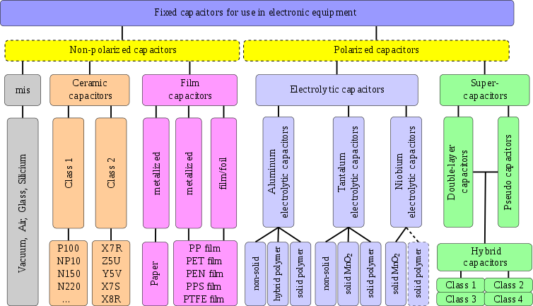
Capacitors are divided into two mechanical groups: Fixed capacitors with fixed capacitance values and variable capacitors with variable (trimmer) or adjustable (tunable) capacitance values.
The most important group is the fixed capacitors. Many got their names from the dielectric. For a systematic classification these characteristics can't be used, because one of the oldest, the electrolytic capacitor, is named instead by its cathode construction. So the most-used names are simply historical.
The most common kinds of capacitors are:
- Ceramic capacitors have a ceramic dielectric.
- Film and paper capacitors are named for their dielectrics.
- Aluminum, tantalum and niobium electrolytic capacitors are named after the material used as the anode and the construction of the cathode (electrolyte)
- Polymer capacitors are aluminum,tantalum or niobium electrolytic capacitors with conductive polymer as electrolyte
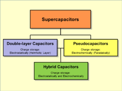
- Supercapacitor is the family name for:
- Double-layer capacitors were named for the physical phenomenon of the Helmholtz double-layer
- Pseudocapacitors were named for their ability to store electric energy electro-chemically with reversible faradaic charge-transfer
- Hybrid capacitors combine double-layer and pseudocapacitors to increase power density
- Silver mica, glass, silicon, air-gap and vacuum capacitors are named for their dielectric.
In addition to the above shown capacitor types, which derived their name from historical development, there are many individual capacitors that have been named based on their application. They include:
- Power capacitors, motor capacitors, DC-link capacitors, suppression capacitors, audio crossover capacitors, lighting ballast capacitors, snubber capacitors, coupling,decoupling or bypassing capacitors.
Often, more than one capacitor family is employed for these applications, e.g. interference suppression can use ceramic capacitors or film capacitors.
Other kinds of capacitors are discussed in the #Special capacitors section.
Dielectrics[edit]
The most common dielectrics are:
- Ceramics
- Plastic films
- Oxide layer on metal (Aluminum, Tantalum, Niobium)
- Natural materials like mica, glass, paper, air, vacuum
All of them store their electrical charge statically within an electric field between two (parallel) electrodes.
Beneath this conventional capacitors a family of electrochemical capacitors called Supercapacitors was developed. Supercapacitors don't have a conventional dielectric. They store their electrical charge statically in Helmholtz double-layers and faradaically at the surface of electrodes
- with static Double-layer capacitance in a double-layer capacitor and
- with pseudocapacitance (faradaic charge transfer) in a Pseudocapacitor
- or with both storage principles together in hybrid capacitors.
The most important material parameters of the different dielectrics used and the appr. Helmholtz-layer thickness are given in the table below.
| Capacitor style | Dielectric | Relative Permittivity at 1 kHz | Maximum/realized. dielectric strength V/µm | Minimum thickness of the dielectric µm |
|---|---|---|---|---|
| Ceramic capacitors, Class 1 | paraelectric | 12–40 | < 100(?) | 1 |
| Ceramic capacitors, Class 2 | ferroelectric | 200–14,000 | < 35 | 0.5 |
| Film capacitors | Polypropylene ( PP) | 2.2 | 650/450 | 1.9 – 3.0 |
| Film capacitors | Polyethylene terephthalate, Polyester (PET) | 3.3 | 580/280 | 0.7–0.9 |
| Film capacitors | Polyphenylene sulfide (PPS) | 3.0 | 470/220 | 1.2 |
| Film capacitors | Polyethylene naphthalate (PEN) | 3.0 | 500/300 | 0.9–1.4 |
| Film capacitors | Polytetrafluoroethylene (PTFE) | 2.0 | 450(?)/250 | 5.5 |
| Paper capacitors | Paper | 3.5–5.5 | 60 | 5–10 |
| Aluminum electrolytic capacitors | Aluminium oxide Al2O3 | 9,6[9] | 710 | < 0.01 (6.3 V) < 0.8 (450 V) |
| Tantalum electrolytic capacitors | Tantalum pentoxide Ta2O5 | 26[9] | 625 | < 0.01 (6.3 V) < 0.08 (40 V) |
| Niobium electrolytic capacitors | Niobium pentoxide, Nb2O5 | 42 | 455 | < 0.01 (6.3 V) < 0.10 (40 V) |
| Supercapacitors Double-layer capacitors | Helmholtz double-layer | - | 5000 | < 0.001 (2.7 V) |
| Vacuum capacitors | Vacuum | 1 | 40 | - |
| Air gap capacitors | Air | 1 | 3.3 | - |
| Glass capacitors | Glass | 5–10 | 450 | - |
| Mica capacitors | Mica | 5–8 | 118 | 4–50 |
The capacitor's plate area can be adapted to the wanted capacitance value. The permittivity and the dielectric thickness are the determining parameter for capacitors. Ease of processing is also crucial. Thin, mechanically flexible sheets can be wrapped or stacked easily, yielding large designs with high capacitance values. Razor-thin metallized sintered ceramic layers covered with metallized electrodes however, offer the best conditions for the miniaturization of circuits with SMD styles.
A short view to the figures in the table above gives the explanation for some simple facts:
- Supercapacitors have the highest capacitance density because of its special charge storage principles
- Electrolytic capacitors have lesser capacitance density than supercapacitors but the highest capacitance density of conventional capacitors because its thin dielectric.
- Ceramic capacitors class 2 have much higher capacitance values in a given case than class 1 capacitors because of their much higher permittivity.
- Film capacitors with their different plastic film material do have a small spread in the dimensions for a given capacitance/voltage value of a film capacitor because the minimum dielectric film thickness differs between the different film materials.
Capacitance and voltage range[edit]
Capacitance ranges from picofarad to more than hundreds of farad. Voltage ratings can reach 100 kilovolts. In general, capacitance and voltage correlates with physical size and cost.
Miniaturization[edit]
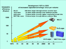
As in other areas of electronics, volumetric efficiency measures the performance of electronic function per unit volume. For capacitors, the volumetric efficiency is measured with the "CV product", calculated by multiplying the capacitance (C) by the maximum voltage rating (V), divided by the volume. From 1970 to 2005, volumetric efficiencies have improved dramatically.
- Miniaturizing of capacitors
Overlapping range of applications[edit]
These individual capacitors can perform their application independent of their affiliation to an above shown capacitor type, so that an overlapping range of applications between the different capacitor types exists.
Types and styles[edit]
Ceramic capacitors[edit]
Main article: Ceramic capacitor
A ceramic capacitor is a non-polarized fixed capacitor made out of two or more alternating layers of ceramic and metal in which the ceramic material acts as the dielectric and the metal acts as the electrodes. The ceramic material is a mixture of finely ground granules ofparaelectric or ferroelectric materials, modified by mixed oxides that are necessary to achieve the capacitor's desired characteristics. The electrical behavior of the ceramic material is divided into two stability classes:
- Class 1 ceramic capacitors with high stability and low losses compensating the influence of temperature in resonant circuit application. Common EIA/IEC code abbreviations are C0G/NP0, P2G/N150, R2G/N220, U2J/N750 etc.
- Class 2 ceramic capacitors with high volumetric efficiency for buffer, by-pass and coupling applications Common EIA/IEC code abbreviations are: X7R/2XI, Z5U/E26, Y5V/2F4, X7S/2C1, etc.
The great plasticity of ceramic raw material works well for many special applications and enables an enormous diversity of styles, shapes and great dimensional spread of ceramic capacitors. The smallest discrete capacitor, for instance, is a "01005" chip capacitor with the dimension of only 0.4 mm × 0.2 mm.
The construction of ceramic multilayer capacitors with mostly alternating layers results in single capacitors connected in parallel. This configuration increases capacitance and decreases all losses and parasitic inductances. Ceramic capacitors are well-suited for high frequencies and high current pulse loads.
Because the thickness of the ceramic dielectric layer can be easily controlled and produced by the desired application voltage, ceramic capacitors are available with rated voltages up to the 30 kV range.
Some ceramic capacitors of special shapes and styles are used as capacitors for special applications, including RFI/EMI suppression capacitors for connection to supply mains, also known as safety capacitors,[10][11] X2Y® and three-terminal capacitors for bypassing and decoupling applications,[12][13] feed-through capacitors for noise suppression by low-pass filters[14] and ceramic power capacitors for transmitters and HF applications.[15][16]
- Diverse styles of ceramic capacitors
Film capacitors[edit]
Main article: Film capacitor
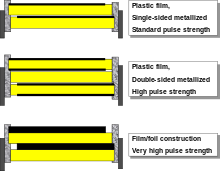
Film capacitors or plastic film capacitors are non-polarized capacitors with an insulating plastic film as the dielectric. The dielectric films are drawn to a thin layer, provided with metallic electrodes and wound into a cylindrical winding. The electrodes of film capacitors may be metallized aluminum or zinc, applied on one or both sides of the plastic film, resulting in metallized film capacitors or a separate metallic foil overlying the film, called film/foil capacitors.
Metallized film capacitors offer self-healing properties. Dielectric breakdowns or shorts between the electrodes do not destroy the component. The metallized construction makes it possible to produce wound capacitors with larger capacitance values (up to 100 µF and larger) in smaller cases than within film/foil construction.
Film/foil capacitors or metal foil capacitors use two plastic films as the dielectric. Each film is covered with a thin metal foil, mostly aluminium, to form the electrodes. The advantage of this construction is the ease of connecting the metal foil electrodes, along with an excellent current pulse strength.
A key advantage of every film capacitor's internal construction is direct contact to the electrodes on both ends of the winding. This contact keeps all current paths very short. The design behaves like a large number of individual capacitors connected in parallel, thus reducing the internal ohmic losses (ESR) and ESL. The inherent geometry of film capacitor structure results in low ohmic losses and a low parasitic inductance, which makes them suitable for applications with high surge currents (snubbers) and for AC power applications, or for applications at higher frequencies.
The plastic films used as the dielectric for film capacitors are Polypropylene (PP), Polyester (PET), Polyphenylene sulfide (PPS), Polyethylene naphthalate (PEN), andPolytetrafluoroethylene or Teflon (PTFE). Polypropylene film material with a market share of something about 50% and Polyester film with something about 40% are the most used film materials. The rest of something about 10% will be used by all other materials including PPS and paper with roughly 3%, each.[17][18]
| Film material, abbreviated codes | |||||
|---|---|---|---|---|---|
| Film characteristics | PET | PEN | PPS | PP | |
| Relative permittivity at 1 kHz | 3.3 | 3.0 | 3.0 | 2.2 | |
| Minimum film thickness (µm) | 0.7–0.9 | 0.9–1.4 | 1.2 | 2.4–3.0 | |
| Moisture absorption (%) | low | 0.4 | 0.05 | <0.1 | |
| Dielectric strength (V/µm) | 580 | 500 | 470 | 650 | |
| Commercial realized voltage proof (V/µm) | 280 | 300 | 220 | 400 | |
| DC voltage range (V) | 50–1,000 | 16–250 | 16–100 | 40–2,000 | |
| Capacitance range | 100 pF–22 µF | 100 pF–1 µF | 100 pF–0.47 µF | 100 pF–10 µF | |
| Application temperature range (°C) | −55 to +125 /+150 | −55 to +150 | −55 to +150 | −55 to +105 | |
| ΔC/C versus temperature range (%) | ±5 | ±5 | ±1.5 | ±2.5 | |
| Dissipation factor (•10−4) | |||||
| at 1 kHz | 50–200 | 42–80 | 2–15 | 0.5–5 | |
| at 10 kHz | 110–150 | 54–150 | 2.5–25 | 2–8 | |
| at 100 kHz | 170–300 | 120–300 | 12–60 | 2–25 | |
| at 1 MHz | 200–350 | – | 18–70 | 4–40 | |
| Time constant RInsul•C (s) | at 25 °C | ≥10,000 | ≥10,000 | ≥10,000 | ≥100,000 |
| at 85 °C | 1,000 | 1,000 | 1,000 | 10,000 | |
| Dielectric absorption (%) | 0.2–0.5 | 1–1.2 | 0.05–0.1 | 0.01–0.1 | |
| Specific capacitance (nF•V/mm3) | 400 | 250 | 140 | 50 | |
Some film capacitors of special shapes and styles are used as capacitors for special applications, including RFI/EMI suppression capacitors for connection to the supply mains, also known as safety capacitors,[19] Snubber capacitors for very high surge currents,[20] Motor run capacitors, AC capacitors for motor-run applications[21]
- High pulse current load is the most important feature of film capacitors so many of the available styles do have special terminations for high currents
Film power capacitors[edit]
A related type is the power film capacitor. The materials and construction techniques used for large power film capacitors mostly are similar to those of ordinary film capacitors. However, capacitors with high to very high power ratings for applications in power systems and electrical installations are often classified separately, for historical reasons. The standardization of ordinary film capacitors is oriented on electrical and mechanical parameters. The standardization of power capacitors by contrast emphasizes the safety of personnel and equipment, as given by the local regulating authority.
As modern electronic equipment gained the capacity to handle power levels that were previously the exclusive domain of "electrical power" components, the distinction between the "electronic" and "electrical" power ratings blurred. Historically, the boundary between these two families was approximately at a reactive power of 200 volt-amperes.
Film power capacitors mostly use polypropylene film as the dielectric. Other types include metallized paper capacitors (MP capacitors) and mixed dielectric film capacitors with polypropylene dielectrics. MP capacitors serve for cost applications and as field-free carrier electrodes (soggy foil capacitors) for high AC or high current pulse loads. Windings can be filled with an insulating oil or with epoxy resin to reduce air bubbles, thereby preventing short circuits.
They find use as converters to change voltage, current or frequency, to store or deliver abruptly electric energy or to improve the power factor. The rated voltage range of these capacitors is from approximately 120 V AC (capacitive lighting ballasts) to 100 kV.[22]
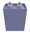
- Power film capacitors for applications in power systems, electrical installations and plants
Electrolytic capacitors[edit]
Main article: Electrolytic capacitor
Electrolytic capacitors have a metallic anode covered with an oxidized layer used as dielectric. The second electrode is a non-solid (wet) or solid electrolyte. Electrolytic capacitors are polarized. Three families are available, categorized according to their dielectric.
- Aluminum electrolytic capacitors with aluminum oxide as dielectric
- Tantalum electrolytic capacitors with tantalum pentoxide as dielectric
- Niobium electrolytic capacitors with niobium pentoxide as dielectric.
The anode is highly roughened to increase the surface area. This and the relatively high permittivity of the oxide layer gives these capacitors very high capacitance per unit volume compared with film- or ceramic capacitors.
The permittivity of tantalum pentoxide is approximately three times higher than aluminium oxide, producing significantly smaller components. However, permittivity determines only the dimensions. Electrical parameters, especially conductivity, are established by the electrolyte's material and composition. Three general types of electrolytes are used:
- non solid (wet, liquid)—conductivity approximately 10 mS/cm and are the lowest cost
- solid manganese oxide—conductivity approximately 100 mS/cm offer high quality and stability
- solid conductive polymer (Polypyrrole or PEDOT:PSS)—conductivity approximately 100...500 S/cm,[23][24] offer ESR values as low as <10 mΩ
Internal losses of electrolytic capacitors, prevailing used for decoupling and buffering applications, are determined by the kind of electrolyte.
| Anode material | Electrolyte | Capacitance range (µF) | Max. rated voltage at 85 °C (V) | Upper categorie temperature (°C) | Specific ripple current (mA/mm3) 1) |
|---|---|---|---|---|---|
| Aluminum (roughned foil) | non solid, e.g. Ethylene glycol, DMF, DMA, GBL | 0.1–2,700,000 | 600 | 150 | 0.05–2.0 |
| solid, Manganese dioxide (MnO2 | 0.1–1,500 | 40 | 175 | 0.5–2.5 | |
| solid conductive polymere (e.g. PEDOT:PSS) | 10–1,500 | 250 | 125 | 10–30 | |
| Tantalum (roughned foil) | non solid Sulfuric acid | 0.1–1,000 | 630 | 125 | – |
| Tantalum (sintered) | non solid sulfuric acid | 0.1–15,000 | 150 | 200 | – |
| solid Manganese dioxide (MnO2 | 0.1–3,300 | 125 | 150 | 1.5–15 | |
| solid conductive polymere (e.g. PEDOT:PSS) | 10–1,500 | 35 | 125 | 10–30 | |
| Niobium or niobium oxide (sintered) | solid Manganese dioxide (MnO2 | 1–1,500 | 10 | 125 | 5–20 |
| |||||
The large capacitance per unit volume of electrolytic capacitors make them valuable in relatively high-current and low-frequency electrical circuits, e.g. in power supply filters for decoupling unwanted AC components from DC power connections or as coupling capacitors in audio amplifiers, for passing or bypassing low-frequency signals and storing large amounts of energy. The relatively high capacitance value of an electrolytic capacitor combined with the very low ESR of the polymer electrolyte of polymer capacitors, especially in SMD styles, makes them a competitor to MLC chip capacitors in personal computer power supplies.
Bipolar aluminum electrolytic capacitors (also called Non-Polarized capacitors) contain two anodized aluminium foils, behaving like two capacitors connected in series opposition.
Electolytic capacitors for special applications include motor start capacitors,[25] flashlight capacitors[26] and audio frequency capacitors.[27]
- Schematic representation
- Aluminum, tantalum and niobium electrolytic capacitors
Supercapacitors[edit]
Main article: Supercapacitor
Supercapacitors (SC),[28] comprise a family of electrochemical capacitors. Supercapacitor, sometimes called ultracapacitor is a generic term for electric double-layer capacitors (EDLC), pseudocapacitors and hybrid capacitors. They don't have a conventional solid dielectric. The capacitance value of an electrochemical capacitor is determined by two storage principles, both of which contribute to the total capacitance of the capacitor:[29][30][31]
- Double-layer capacitance – Storage is achieved by separation of charge in a Helmholtz double layer at the interface between the surface of a conductor and an electrolytic solution. The distance of separation of charge in a double-layer is on the order of a fewAngstroms (0.3–0.8 nm). This storage is electrostatic in origin.[3]
- Pseudocapacitance – Storage is achieved by redox reactions, electrosorbtion or intercalation on the surface of the electrode or by specifically adsorpted ions that results in a reversible faradaic charge-transfer. The pseudocapacitance is faradaic in origin.[3]
The ratio of the storage resulting from each principle can vary greatly, depending on electrode design and electrolyte composition. Pseudocapacitance can increase the capacitance value by as much as an order of magnitude over that of the double-layer by itself.[28]
Supercapacitors are divided into three families, based on the design of the electrodes:
- Double-layer capacitors – with carbon electrodes or derivates with much higher static double-layer capacitance than the faradaic pseudocapacitance
- Pseudocapacitors – with electrodes out of metal oxides or conducting polymers with a high amount of faradaic pseudocapacitance
- Hybrid capacitors – capacitors with special and asymmetric electrodes that exhibit both significant double-layer capacitance and pseudocapacitance, such as lithium-ion capacitors
Supercapacitors bridge the gap between conventional capacitors and rechargeable batteries. They have the highest available capacitance values per unit volume and the greatest energy density of all capacitors. They support up to 12,000 Farads/1.2 Volt,[32]with capacitance values up to 10,000 times that of electrolytic capacitors.[28] While existing supercapacitors have energy densities that are approximately 10% of a conventional battery, their power density is generally 10 to 100 times greater. Power density is defined as the product of energy density, multiplied by the speed at which the energy is delivered to the load. The greater power density results in much shorter charge/discharge cycles than a battery is capable, and a greater tolerance for numerous charge/discharge cycles. This makes them well-suited for parallel connection with batteries, and may improve battery performance in terms of power density.
Within electrochemical capacitors, the electrolyte is the conductive connection between the two electrodes, distinguishing them from electrolytic capacitors, in which the electrolyte only forms the cathode, the second electrode.
Supercapacitors are polarized and must operate with correct polarity. Polarity is controlled by design with asymmetric electrodes, or, for symmetric electrodes, by a potential applied during the manufacturing process.
Supercapacitors support a broad spectrum of applications for power and energy requirements, including:
- Low supply current during longer times for memory backup in (SRAMs) in electronic equipment
- Power electronics that require very short, high current, as in the KERSsystem in Formula 1 cars
- Recovery of braking energy for vehicles such as buses and trains
Supercapacitors are rarely interchangeable, especially those with higher energy densities. IEC standard 62391-1 Fixed electric double layer capacitors for use in electronic equipment identifies four application classes:
- Class 1, Memory backup, discharge current in mA = 1 • C (F)
- Class 2, Energy storage, discharge current in mA = 0.4 • C (F) • V (V)
- Class 3, Power, discharge current in mA = 4 • C (F) • V (V)
- Class 4, Instantaneous power, discharge current in mA = 40 • C (F) • V (V)
Exceptional for electronic components like capacitors are the manifold different trade or series names used for supercapacitors like: APowerCap, BestCap, BoostCap, CAP-XX, DLCAP, EneCapTen, EVerCAP, DynaCap, Faradcap, GreenCap, Goldcap, HY-CAP, Kapton capacitor, Super capacitor, SuperCap, PAS Capacitor, PowerStor, PseudoCap, Ultracapacitor making it difficult for users to classify these capacitors.
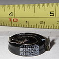
- Double-layer, Lithium-Ion and supercapacitors
Class X and Class Y capacitors[edit]
Many safety regulations mandate that Class X or Class Y capacitors must be used whenever a "fail-to-short-circuit" could put humans in danger, to guarantee galvanic isolationeven when the capacitor fails.
Lightning strikes and other sources cause high voltage surges in mains power. Safety capacitors protect humans and devices from high voltage surges by shunting the surge energy to ground.[33]
In particular, safety regulations mandate a particular arrangement of Class X and Class Y mains filtering capacitors. [34]
In principle, any dielectric could be used to build Class X and Class Y capacitors; perhaps by including an internal fuse to improve safety.[35][36][37][38] In practice, capacitors that meet Class X and Class Y specifications are typically ceramic RFI/EMI suppression capacitors or plastic film RFI/EMI suppression capacitors.
Miscellaneous capacitors[edit]
Beneath the above described capacitors covering more or less nearly the total market of discrete capacitors some new developments or very special capacitor types as well as older types can be found in electronics.
Integrated capacitors[edit]
- Integrated capacitors—in integrated circuits, nano-scale capacitors can be formed by appropriate patterns of metallization on an isolating substrate. They may be packaged in multiple capacitor arrays with no other semiconductive parts as discrete components.[39]
- Glass capacitors—First Leyden jar capacitor was made of glass, As of 2012 glass capacitors were in use as SMD version for applications requiring ultra-reliable and ultra-stable service.
Power capacitors[edit]
- Vacuum capacitors—used in high power RF transmitters
- SF6 gas filled capacitors—used as capacitance standard in measuring bridge circuits
Special capacitors[edit]
- Printed circuit boards—metal conductive areas in different layers of a multi-layer printed circuit board can act as a highly stable capacitor. It is common industry practice to fill unused areas of one PCB layer with the ground conductor and another layer with the power conductor, forming a large distributed capacitor between the layers.
- Wire—2 pieces of insulated wire twisted together. Capacitance values usually range from 3 pF to 15 pF. Used in homemade VHF circuits for oscillation feedback.
Specialized devices such as built-in capacitors with metal conductive areas in different layers of a multi-layer printed circuit board and kludges such as twisting together two pieces of insulated wire also exist.
Capacitors made by twisting 2 pieces of insulated wire together are called gimmick capacitors. Gimmick capacitors were used in commercial and amateur radio receivers.[40][41][42][43][44]
Obsolete capacitors[edit]
- Leyden jars the first capacitors ever
- Mica capacitors—the first capacitors with stable frequency behavior and low losses, used for military radio applications during World War II
- Air-gap capacitors—used by the first spark-gap transmitters
- Miscellaneous capacitors
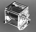
Variable capacitors[edit]
Variable capacitors may have their capacitance changed by mechanical motion. Generally two versions of variable capacitors has to be to distinguished
- Tuning capacitor – variable capacitor for intentionally and repeatedly tuning an oscillator circuit in a radio or another tuned circuit
- Trimmer capacitor – small variable capacitor usually for one-time oscillator circuit internal adjustment
Variable capacitors include capacitors that use a mechanical construction to change the distance between the plates, or the amount of plate surface area which overlaps. They mostly use air as dielectric medium.
Semiconductive variable capacitance diodes are not capacitors in the sense of passive components but can change their capacitance as a function of the applied reverse bias voltage and are used like a variable capacitor. They have replaced much of the tuning and trimmer capacitors.
- Variable capacitors















تعليقات
إرسال تعليق